Case Studies
Case Studies
- Construction of A New Organic-inorganic Composite Emulsion and Its Enhanced Mechanical Properties of Oil Well Cement(Part 1)
- Construction of A New Organic-inorganic Composite Emulsion and Its Enhanced Mechanical Properties of Oil Well Cement(Part 2)
- The Application Prospects of DeepSeek Large Model in Petroleum Engineering(Part 1)
- The Application Prospects of DeepSeek Large Model in Petroleum Engineering(Part 2)
- Development and Performance Evaluation of Efficient Asphalt Dispersant (Part 1)
- Development and Performance Evaluation of Efficient Asphalt Dispersant (Part 2)
- Development and Performance Evaluation of Efficient Asphalt Dispersant (Part 3)
- Research and Application Status of Drilling Fluid Plugging Materials (Part 1)
- Research and Application Status of Drilling Fluid Plugging Materials (Part 2)
- Research and Application Status of Drilling Fluid Plugging Materials (Part 3)
2.2 Formation and Structural Analysis of Stable Sealing Wall Surface
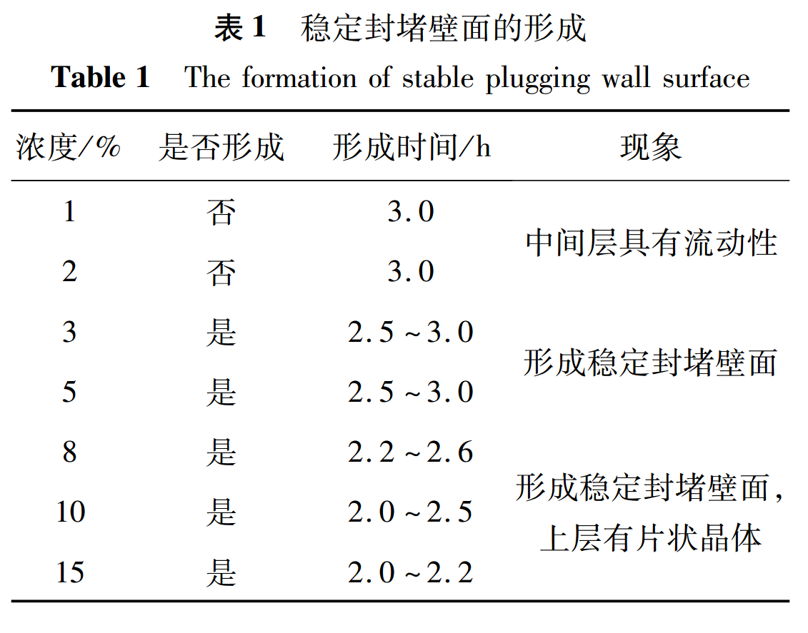
Add different concentrations of sealing agents to water and observe the stable stroke of the sealing wall. The results are shown in Table 1.The minimum concentration of sealing agent required to form a stable sealing wall is about 3%.When the concentration is below 3%, the middle wall has fluidity. When the concentration is above 3% but below 5%, the middle wall has good wall adhesion and no fluidity.When the concentration of the sealing agent is higher than 6%, after forming a stable sealing wall, sheet-like crystals can be observed in the upper layer, indicating that there is a significant amount of sealing agent that has not participated in the formation of the intermediate stable sealing wall.Therefore, the concentration of the sealing agent for forming a stable sealing wall is determined to be 3%~5%, and the time for stable sealing wall formation decreases with the increase of the concentration of the sealing agent, indicating that the amount of sealing agent used will affect the formation process of the stable sealing wall. That is, the aggregation rate of the sealing agent at the oil-water interface affects the formation rate of the stable sealing wall, but the total formation time is not less than 2 hours, which limits the practical application of the sealing agent.

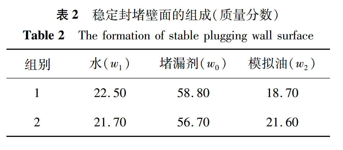
Perform component analysis on the stable sealing wall formed. Take out the stable sealing wall and weigh it, with a mass of m. The mass of the original water in the system is m1, and the mass of the original simulated oil is m2; After forming a stable sealing wall, the remaining water mass of the system is m3, and the remaining simulated oil mass is m4. The composition w1, w2, and w0 of the stable sealing wall can be obtained through the formula, which is the ratio of water, oil, and sealing agent. The results are shown in Table 2.The results showed that the stable wall had a water content of 22.10%, an oil content of 20.15%, and a plugging agent content of 57.75% (all of which are averages).The sealing agent is the main component for stabilizing the sealing wall, which contains a large amount of water and simulated oil, which can reduce the pollution of the formation by the sealing agent after mud injection.

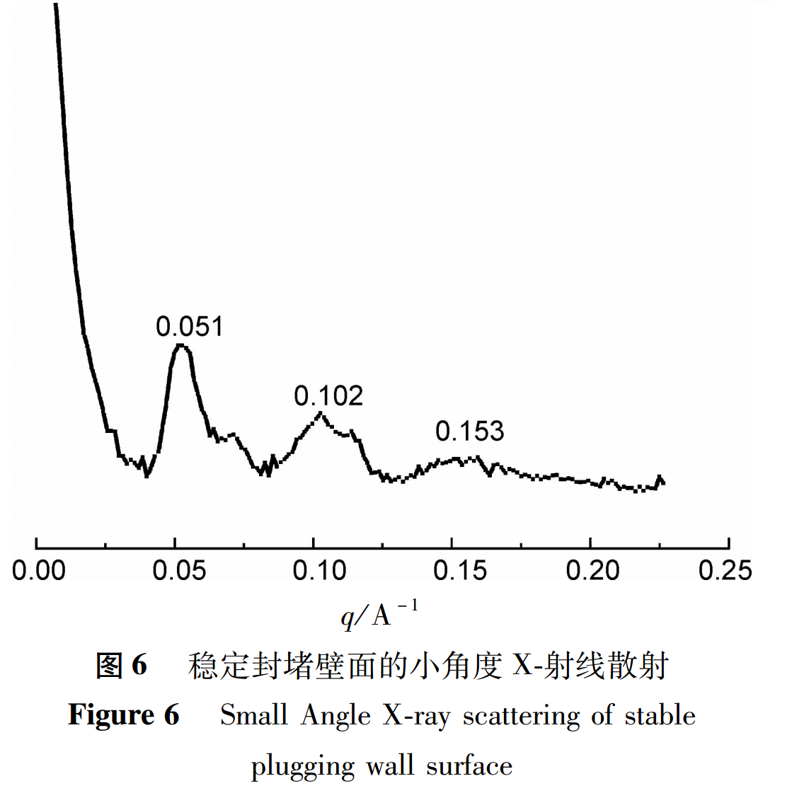
The stable sealing wall was removed for small angle X-ray scattering analysis, and the results are shown in Figure 6.The obvious scattering peak is shown in Figure 6, where the transverse axis scattering factor q (1): q (2): q (3)=1:2:3, indicating that the stable plugging wall exists in a layered liquid crystal gel structure. The layered arrangement of the stable sealing wall is calculated based on X-ray scattering data, Bragg formula, and the specific composition ratio of the stable sealing wall.

The length of the sealing agent molecule was calculated to be 34.69Å using Materials Studio software, and the molecular structure of the sealing agent is shown in Figure 7 (a).The stable sealing wall structure formed by the sealing agent is shown in Figure 7 (b). In the microstructure of the stable sealing wall, the sealing agent forms a layered structure between water and simulated oil in the form of hydrophobic carbon chains inside and hydrophilic head groups outside. The oil phase exists between the hydrophobic carbon chains of the sealing agent, and water molecules exist between the bilayer.The Materials Studio software provides a stable sealing wall structure as shown in Figure 7 (c), where the sealing agent molecules aggregate and entangle to form a stable sealing wall. Only a small amount of water and simulated oil are encapsulated in the sealing agent chain, while the large amount of water and simulated oil present in the system do not participate in the formation of a stable sealing wall.
Fig 7(a).png)
.png)
2.3 Stable Sealing Wall Pressure Resistance Evaluation
The compressive strength of the stable sealing wall formed by the contact between the sealing agent and formation water in cracks of different sizes is simulated using a simple connecting device for the structure of formation fractures, as shown in Table 3.For the connector device, due to the limitation of oil-water contact surface, although the total volume of the stable sealing wall formed is relatively small, it can withstand the compression of formation water or working fluid of 100 times its own mass, indicating that the stable sealing wall can exist stably in formation fractures for a long time.The inverted pressure test confirms that the formed stable sealing wall can withstand a gravity pressure of 100 times its own mass of formation water, and can maintain pressure for more than 30 days without deformation, indicating that the formed stable sealing wall has good pressure bearing performance.At the same time, the stable sealing wall in the inverted device not only faces the vertical gravity compression of water, but also the adhesion effect between the stable sealing wall and the channel wall.Inverted pressure confirms that the stable sealing wall not only has strong pressure bearing capacity, but also has good adhesion ability, which enables the stable sealing wall to effectively achieve adhesion and sealing of channels in formation fractures.The pressure bearing area of the stable sealing wall, the gravity of the upper layer water, the pressure per unit area of the stable sealing wall, and the pressure per unit mass of the sealing agent can be calculated according to the formula.
.png)
Therefore, for a 4mm diameter connector, the stable sealing wall pressure per unit area is p=3.90×10⁴Pa, and the stable sealing wall pressure per unit area per unit mass is pw=7.80×10⁷Pa/kg.For a 50mL measuring cylinder, the stable sealing wall formed has a unit area pressure of p=1.417×10³Pa, and the stable sealing wall pressure per unit area per unit mass is pw=2.2834×10⁶Pa/kg;Under the above pressure conditions, it can remain stable for more than 3 days.For a 100mL measuring cylinder, the stable sealing wall formed has a unit area pressure of p=1.847×10³Pa, and the stable sealing wall pressure per unit area per unit mass is pw=3.694×10⁶Pa/kg.The above data indicates that the stable sealing wall formed by the sealing agent in microchannels such as cracks has a unit mass stable sealing wall pressure per unit area of pw=7.80×10⁷Pa/kg, which is 78MPa/kg, and can meet the pressure of most formations.
2.4 Evaluation of the Effect of Temperature on Stable Blocking Wall Surface
The stable sealing wall formed at room temperature was placed in water baths at different temperatures for 30 minutes to observe the stability of the stable sealing wall at different temperatures. The results are shown in Table 4.When the temperature is below 65℃, the stable sealing wall has good wall adhesion and pressure bearing ability; When the temperature exceeds 75℃, the stable sealing wall completely loses its solid stability and exhibits good fluidity; When the temperature range is 65-75℃, the flowability becomes better and the solid-state stability becomes worse, indicating that the stable blocking wall has good ability to block channels at temperatures below 65℃.
.png)
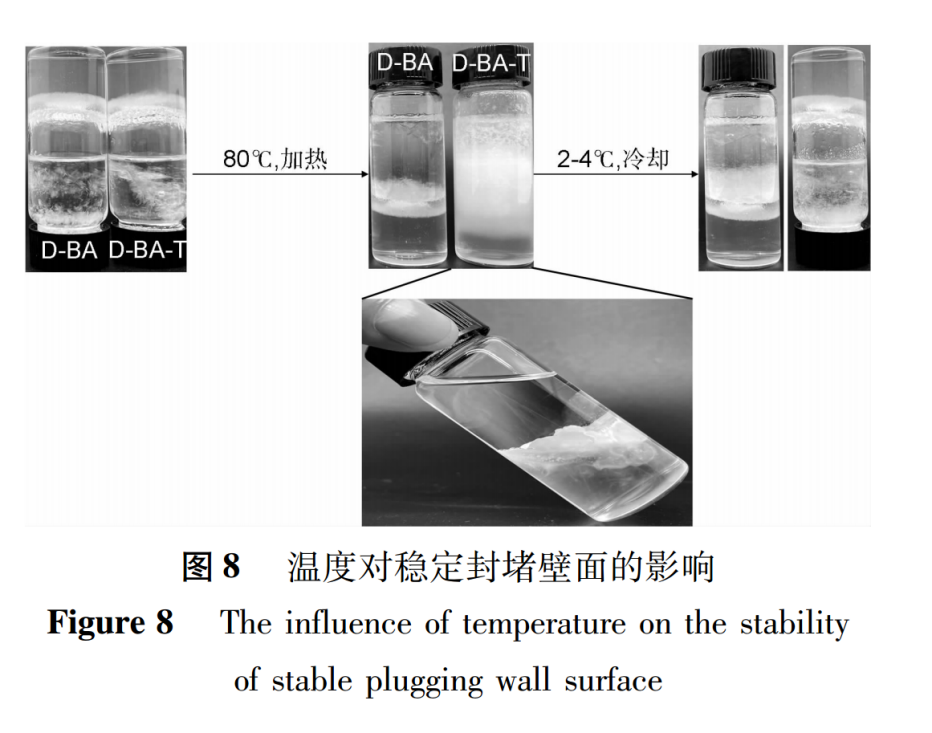
The stable sealing wall formed at room temperature was heated in 80℃ water bath for 30min, and changed from non flowing layered gel to flowing state (Figure 8). The stable sealing wall lost its stability and sealing effect on fractures.Transfer it to cold storage, and the stable sealing wall reappears, restoring the sealing of the crack, indicating that the stable sealing wall has temperature responsiveness.

3.Conclusion
This article presents a novel responsive worm like micelle plugging agent suitable for medium and low temperature leakage layers synthesized by a one-step method using N, N-dimethylcyclohexylamine (DMCHA) and behenic acid (BA).The sealing agent dissolves in simulated oil and forms a stable sealing wall when in contact with water; The stable wall is a lamellar liquid crystal gel structure with a layer spacing of 123.20Å.In a 4mm connected pipeline, the unit mass of sealing agent can withstand a pressure of 78MPa and stabilize for more than 30 days, confirming that the stable wall has good pressure bearing and pressure resistance capabilities; The inverted pressure test confirms that the stable wall has good adhesion to the formation, which can achieve effective sealing of the formation.The stable wall can maintain good solid-state stability at temperatures below 65℃, confirming its excellent temperature resistance; And after losing its solid-state stability at 80℃, it can quickly transition from a flowing state to a stable wall surface that does not flow at low temperatures of 2-4℃, confirming that the stable wall surface has good temperature responsiveness.
This new responsive worm like micelle plugging agent has been successfully synthesized and has good plugging performance for medium and low temperature leakage layers. It can also be used as a pre plug for cement plugging to deal with malignant leakage.


