Case Studies
Case Studies
- Construction of A New Organic-inorganic Composite Emulsion and Its Enhanced Mechanical Properties of Oil Well Cement(Part 1)
- Construction of A New Organic-inorganic Composite Emulsion and Its Enhanced Mechanical Properties of Oil Well Cement(Part 2)
- The Application Prospects of DeepSeek Large Model in Petroleum Engineering(Part 1)
- The Application Prospects of DeepSeek Large Model in Petroleum Engineering(Part 2)
- Development and Performance Evaluation of Efficient Asphalt Dispersant (Part 1)
- Development and Performance Evaluation of Efficient Asphalt Dispersant (Part 2)
- Development and Performance Evaluation of Efficient Asphalt Dispersant (Part 3)
- Research and Application Status of Drilling Fluid Plugging Materials (Part 1)
- Research and Application Status of Drilling Fluid Plugging Materials (Part 2)
- Research and Application Status of Drilling Fluid Plugging Materials (Part 3)
2.3 Viscoelastic Comparison
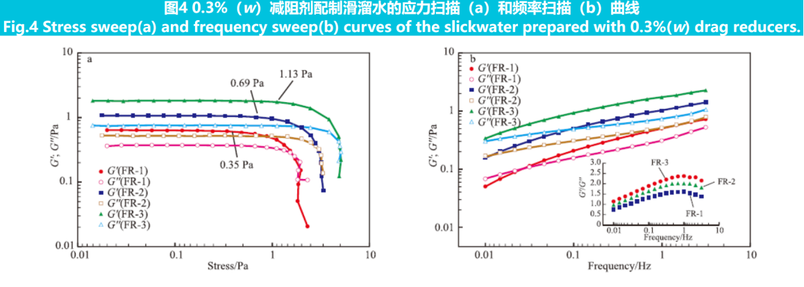
The viscoelasticity of fracturing fluid is closely related to its sand carrying capacity. The viscoelasticity of slippery water prepared by adding 0.3% (w) of three drag reducing agents to tap water was compared. The results of stress scanning and frequency scanning are shown in Figure 4.
From Figure 4a, it can be seen that as the scanning stress increases, the elastic modulus (G') and viscous modulus (G'') of the sample remain unchanged. Beyond a certain critical value (which is the maximum linear stress, also known as yield stress), G' and G'' both rapidly decrease. The yield stresses of the three samples are 0.35, 0.69, and 1.13 Pa, respectively. The higher the yield stress, the higher the structural strength. A higher structural strength is more conducive to improving the suspension effect of the proppant.
From Figure 4b, it can be seen that all three slippery water samples exhibit characteristics of high frequency region G' greater than G'' and low frequency region G' less than G''. The intersection point of G' and G'' in the slippery water prepared with FR-2 and FR-3 tends towards the low frequency region, and the reciprocal of the corresponding frequency at the intersection point is called relaxation time(τ),The longer the τ is, the more it leans towards the elastic body; At the same frequency, the G'/G'' of slippery water prepared with FR-2 and FR-3 is higher. Both τ and G'/G'' indicate that the proportion of elastic characteristics in the preparation of slippery water with micro crosslinked drag reducing agents is higher, and the introduction of chemical crosslinking points promotes the transition of the fluid from viscosity to elasticity, which is more conducive to improving the suspension ability of the proppant.

2.4 Comparison of Sand Carrying Capacity
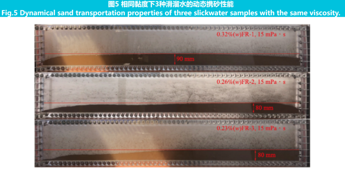
The results of viscoelasticity testing have more guiding significance for the static or quasi-static sand carrying capacity of slippery water. However, in practical applications, the carrying capacity of slippery water on proppant is in a dynamic process. A parallel plate crack simulation device was used to further qualitatively investigate the dynamic sand carrying capacity of slippery water with a viscosity of 15 mPa·s prepared by three drag reducing agents. The result is shown in Figure 5.

From Figure 5, it can be seen that although the viscosity of slippery water is the same, there are still certain differences in sand carrying capacity. For the FR-1 prepared slippery water, its sand embankment has the characteristic of "high in the middle and low on both sides", with the highest sand embankment height of 90 mm; The slippery water sand embankment prepared with FR-2 and FR-3 exhibits a "low front and high back" characteristic, with the highest sand embankment height being 80 mm; The slippery water prepared with FR-3 has the least settlement at the proximal end, indicating its strongest proppant transport ability.
Compared to linear drag reducing agents, micro crosslinked drag reducing agents can obtain slippery water with the same viscosity at lower usage, and the dynamic support agent has a longer migration distance and a better sand laying profile.During the dynamic flow process, linear molecules are more likely to undergo entanglement along the flow field orientation when subjected to high-speed shear. However, micro crosslinking agents and drag reducing agents contain more stable chemical crosslinking structures, which can ensure the density of network structures in the solution and endow slippery water with relatively higher viscoelasticity, resulting in better dynamic sand carrying performance.
2.5 Degradation Performance
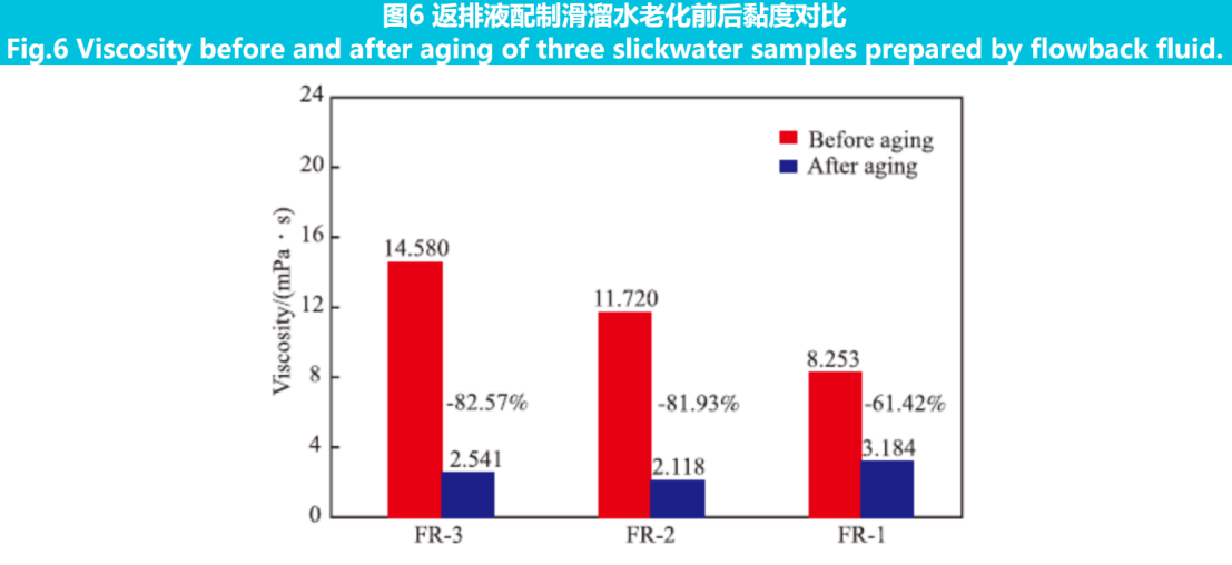
After fracturing, it is required that the polymer in the drag reducing agent can be degraded into small molecular fragments. On the one hand, it reduces the viscosity of the backflow fluid, which helps to discharge the fluid; On the other hand, it reduces the adsorption and retention of polymers in the formation, reducing damage to the reservoir. The molecular size of polymers is larger than that of linear polymers, and it is more important to pay attention to their degradation ability. Using fracturing flowback fluid (mineralization degree 8500 mg/L) to prepare slippery water with a 0.3% (w) addition of drag reducing agent, aging at 90℃ in a high-temperature roller furnace for 48 hours, simulating the degradation conditions of drag reducing agent in the formation. The viscosity changes of slippery water before and after aging were compared, rusult as shown in Figure 6.

From Figure 6, it can be seen that the viscosity reduction rate of the slippery water prepared with micro crosslinked drag reducing agent after aging reaches over 80%, with a significant decrease compared to the linear drag reducing agent, and the absolute viscosity value is also lower, indicating that the degradation performance is better than that of the linear drag reducing agent. On the one hand, under high temperature conditions, the main chain of drag reducing agent molecules undergoes thermal degradation and chain breakage, resulting in a decrease in the viscosity of slippery water; On the other hand, the acrylic ester bonds in multifunctional crosslinking agents undergo hydrolysis under high temperature, generating carboxylic groups and alcohols. Especially, calcium and magnesium ions in formation water are easily bound to carboxylic groups, which can further promote ester bond hydrolysis. The cross-linked structure is hydrolyzed and destroyed, resulting in a significant reduction in molecular size, making the gel breaking of slippery water more thorough. Therefore, the degradation performance is better than that of linear drag reducing agents, thus achieving the goal of protecting the reservoir.
2.6 Field Applications
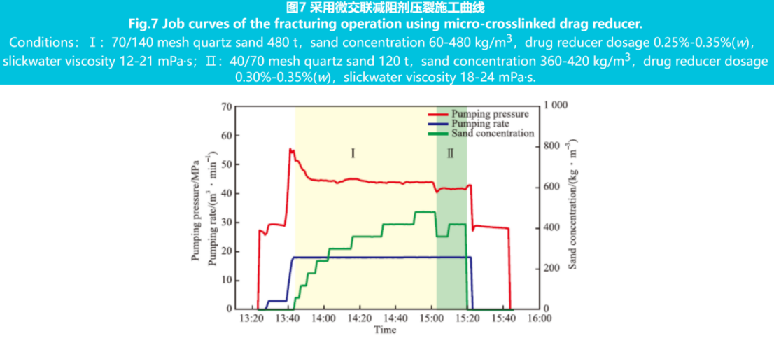
The micro crosslinked drag reducing agent was tested on-site in a well in Jinqian, a tight gas reservoir of the Shaximiao Formation in Sichuan Basin.This well is a horizontal development well, which is undergoing fracturing transformation in 10 sections. The design fluid volume of a single section is 1600-1800 m3, and the sand volume is 530-600 tons. Among them, 70/140 mesh quartz sand is 420-480 tons, 40/70 mesh coated sand is 110-120 tons, with a sand adding strength of 5 t/m, a design construction displacement of 16-18 m3/min, and a maximum sand mass concentration of 480 kg/m3.
The main body adopts medium to high viscosity slippery water, with a quartz sand stage drag reducing agent dosage of 0.25%~0.35% (w), and a slippery water viscosity of 12-21 mPa·s; In the stage of coated sand, the dosage of drag reducing agent is 0.3%~0.35% (w), and the viscosity of slippery water is 18-24 mPa·s; During the replacement phase, use low viscosity slippery water (6-9 mPa·s).
The 4th~6th sections of the well were compared using micro crosslinked drag reducing agents, while the remaining 7 sections used linear drag reducing agents. The construction curve of the 4th section is shown in Figure 7. The pressure of the construction section using micro crosslinked drag reducing agent is stable, and the viscosity and sand carrying capacity of the slippery water sampling on site are normal. The average amount of drag reducing agent added is 0.32% (w), while the average amount of linear drag reducing agent added in the other 7 sections is 0.41% (w). The use of micro crosslinked drag reducing agent decreased by 22%.

3. Conclusion
1) .The dissolution time of micro crosslinked drag reducing agents is about 30-40 seconds, and the drag reduction rate is over 70%, which is equivalent to linear drag reducing agents; The introduction of micro crosslinked structures does not affect the dissolution and drag reduction effects, and can meet the requirements of on-site continuous mixing construction.
2) .The introduction of chemical cross-linking structure in micro crosslinked drag reducing agents has stronger viscosity increasing ability than linear drag reducing agents; The more the average number of functional groups in the crosslinking agent, the stronger its viscosity increasing ability; However, as the amount of drag reducing agent added in slippery water increases, the proportion of chemical crosslinking decreases compared to physical entanglement, and the effect gradually decreases, while the trend of viscosity increase slows down.
3) .Compared to linear drag reducing agents, the network structure of slippery water prepared with micro crosslinked drag reducing agents is more dense, with a higher proportion of elastic characteristics, which helps to improve the suspension ability of the proppant. The dynamic proppant has a longer migration distance and a better sand laying profile.
4) .The ester bonds of multifunctional crosslinking agents in micro crosslinked drag reducing agents will undergo hydrolysis under geological conditions, damaging the cross-linking structure, making the gel breaking of smooth water more thorough and achieving the goal of protecting the reservoir.
5) .The addition amount of micro crosslinked drag reducing agent for on-site use is reduced by more than 20% compared to linear drag reducing agent, which can reduce the cost of fracturing fluid, reduce reservoir damage, and achieve cost reduction and efficiency increase.


