Case Studies
Case Studies
- Construction of A New Organic-inorganic Composite Emulsion and Its Enhanced Mechanical Properties of Oil Well Cement(Part 1)
- Construction of A New Organic-inorganic Composite Emulsion and Its Enhanced Mechanical Properties of Oil Well Cement(Part 2)
- The Application Prospects of DeepSeek Large Model in Petroleum Engineering(Part 1)
- The Application Prospects of DeepSeek Large Model in Petroleum Engineering(Part 2)
- Development and Performance Evaluation of Efficient Asphalt Dispersant (Part 1)
- Development and Performance Evaluation of Efficient Asphalt Dispersant (Part 2)
- Development and Performance Evaluation of Efficient Asphalt Dispersant (Part 3)
- Research and Application Status of Drilling Fluid Plugging Materials (Part 1)
- Research and Application Status of Drilling Fluid Plugging Materials (Part 2)
- Research and Application Status of Drilling Fluid Plugging Materials (Part 3)
Abstract
Shale oil and gas, tight oil and gas, and other unconventional oil and gas reservoirs generally use smooth hydraulic fracturing fluid for large-scale volume fracturing. Due to the low viscosity (less than 5 mPa·s), high filtration loss, and weak carrying capacity of proppant in conventional slickwater, there is a high risk of "sand blockage" during construction; On the other hand, the sand content in slickwater is difficult to increase (usually not exceeding 200 kg/m3). In order to carry sufficient proppant to achieve effective support for hydraulic fractures, it is often necessary to inject a large amount of fracturing fluid, forming the process characteristics of "ten thousand cubic meters of water and one thousand cubic meters of sand", which not only increases fracturing costs but also consumes water resources. Improving the viscosity of slippery water can improve the carrying capacity of proppants. Currently, medium to high viscosity slippery water (10-30 mPa·s) mainly increases viscosity by increasing the content of drag reducing agents. However, increasing the amount of drag reducing agents will lead to a significant increase in the cost of slippery water, and more polymer will be injected into the formation, increasing the damage to reservoir permeability.
How to obtain high viscosity slippery water with low dosage of drag reducing agents is currently an important development direction in the research and development of drag reducing agent technology. Aiming at the problems of poor thickening ability and high usage of conventional linear drag reducers in the preparation of middle-high viscosity slickwater,novel degradable micro-crosslinked drag reducers were developed by introducing crosslinker structure containing acrylate bond into the linear drag reducers.
The experimental results show that crosslinked drag reducers can be dissolved in 30-40 s,and their drag reduction rate can reach over 70%. The thickening ability of crosslinked drag reducers is stronger than that of linear ones,but when the addition is over 0.4%(w),the increasing trend of slickwater viscosity becomes slower. When the slickwater viscosity is required to be 10-30 mPa·s,the adiition of the crosslinked drag reducers can decrease by 20%-30%(w) compared with that of linear ones. The slickwater prepared by the crosslinked drag reducers demonstrates higher yield strength,longer relaxation time and higher ratio of elastic modulus to viscous modulus than by linear ones,indicating higher proportion of elastic characteristics of the slickwater. Slippery water prepared with micro crosslinked drag reducers has a longer dynamic migration distance of proppant and better sand profile. The crosslinked drag reducers can be degraded in formation water,and the viscosity reduction rate of slickwater exceeded 80% after 48h at 90 ℃. The application effect of the crosslinked drag reducers is remarkable,and their amount is more than 20% lower than that of conventional drag reducers.
1. Experimental Part
1.1 Main Reagents and Instruments
- Acrylamide (AM), acrylic acid (AA), 2-acrylamide-2-methylpropanesulfonic acid (AMPS), NaOH, disodium ethylenediaminetetraacetic acid, Tween-80, Span-80, 5 # white oil: industrial products, Chengdu Fangzheng Chemical Co., Ltd;
- Azodiisobutyl imidazoline hydrochloride (AIBI), ammonium persulfate (APS), sodium bisulfite (SHS): analytical pure, Shanghai Aladdin Biochemical Technology Co., Ltd;
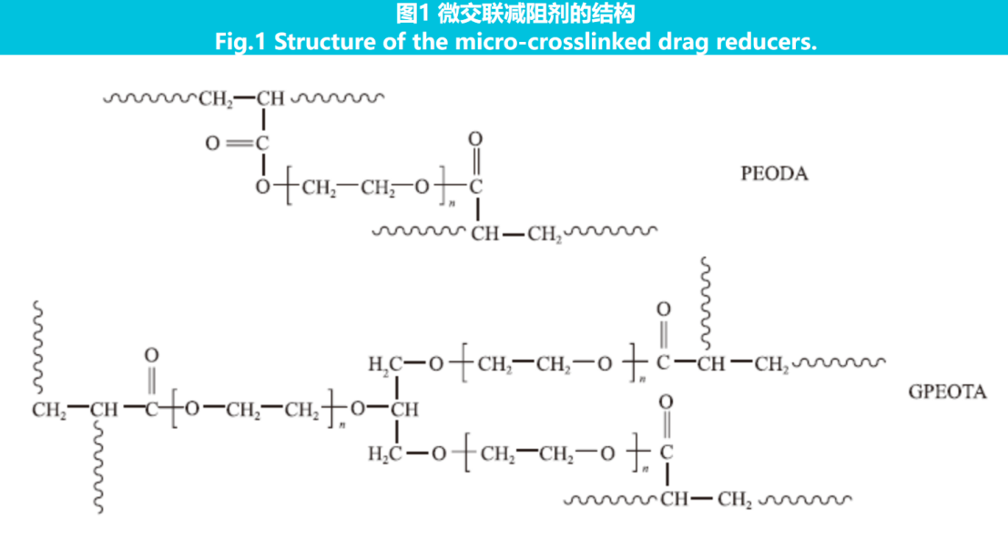
- PEODA and GPEOTA: self-made in the laboratory, with the structure shown in Figure 1.

- HAAKE MARS40 rotary rheometer: Thermo Fisher Scientific;
- HAMZ-II multi pipeline fluid friction tester: Chengdu Core Technology Co., Ltd;
- Roller heating furnace: Qingdao Tongchun Petroleum Instrument Co., Ltd;
- Parallel plate crack simulation device: independently developed by the laboratory.
1.2 Experimental Methods
1.2.1 Preparation of Drag Reducing Agents
- Dissolve an appropriate amount of AM, AA, AMPS (total monomer mass 30 phr) in 30 phr distilled water, adjust pH=7 with NaOH, and then add 0.05 phr crosslinking agent, disodium ethylenediaminetetraacetic acid, and 1 phr Tween-80 to prepare an aqueous phase;
- Add 4 phr of Span-80 to 35 phr of 5 # white oil to form an oil phase;
- Gradually add the aqueous phase into the oil phase, stir at high speed to prepare lotion, and then transfer it to the reaction kettle. The stirring speed is 100~150 r/min, and nitrogen is supplied for 30 minutes;
- At an initial temperature of 10 ℃, gradually add 0.05 phr of initiator, with AIBI, APS, and SHS in a ratio of 1.5 : 2 : 1. Continue the reaction for 8 hours to obtain the finished drag reducing agent (the drag reducing agent containing crosslinking agent PEODA is named FR-2, and the drag reducing agent containing crosslinking agent GPEOTA is named FR-3).
The preparation method of linear drag reducing agent is the same as above (without crosslinking agent, other components and mass fractions are the same), named FR-1.
1.2.2 Solubility and Drag Reduction Rate Test
According to the industry standard NB/T 14003.2-2016 of the Ministry of Energy, use φ10 mm pipeline with a length of 4 meters, a flow rate of 12 m/s inside the pipeline, and a drag reducing agent dosage of 0.1% (w).
1.2.3 Viscosity Test
Using HAAKE MARS40 rotary rheometer and DG41 double slit testing system, with a shear rate of 170 s-1 and a testing temperature of 25 ℃.
1.2.4 Viscoelastic Test
Using HAAKE MARS40 rotary rheometer and PP60 parallel plate testing system, with a seam height of 1mm;
Firstly, a stress scanning mode is used to determine the linear viscoelastic zone of the sample, with a fixed frequency of 1 Hz and a stress range of 0.01-10 Pa; Then perform frequency scanning, with the stress value taken as 80% of the maximum linear stress, and the scanning frequency ranging from 0.01 to 10 Hz.
1.2.5 Proppant Transport Experiment
Using a parallel plate crack simulation device, simulate a crack length of 4000 mm, a crack height of 400 mm, and a crack width of 6 mm;
The viscosity of the slippery water was tested at 15 mPa·s, with a mass concentration of 150 kg/m3 of 40/70 mesh ceramic particle proppant sand, a total liquid volume of 100 L, and an experimental displacement of 800 L/h.
2. Results and Discussion
2.1 Solubility and Drag Reduction Rate
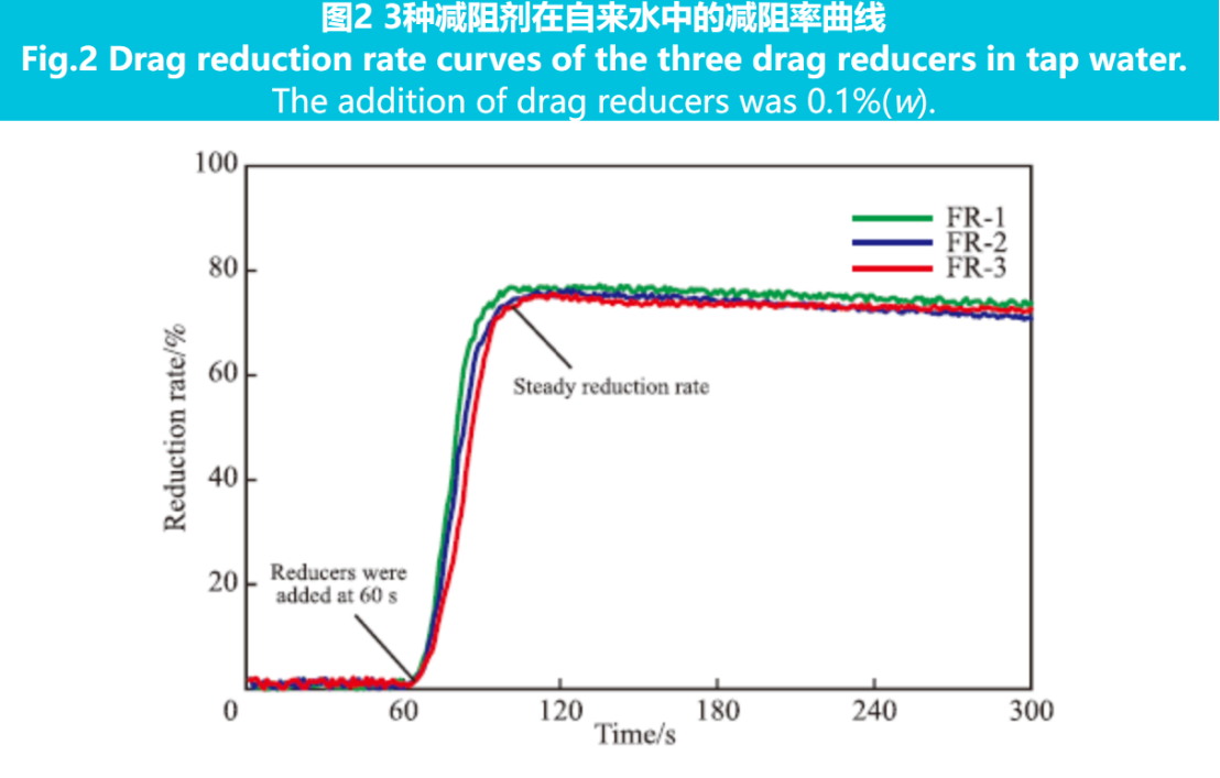
The dissolution rate and drag reduction rate of three drag reducing agents were investigated in tap water at a dosage of 0.1% (w). The drag reduction rate curve is shown in Figure 2.
From Figure 2, it can be seen that after adding drag reducing agent for 30-40 seconds, the drag reduction rate can basically reach stability, indicating that the dissolution time of the drag reducing agent is 30-40 seconds, which can meet the needs of continuous mixing construction on site; And the drag reduction rate remains above 70% throughout the testing time, meeting the requirements of NB/T 14003.2-2016 standard. The drag reduction rate curves of micro crosslinked drag reducing agents FR-2, FR-3, and linear drag reducing agent FR-1 remain highly consistent, indicating that the introduction of micro crosslinked structure does not affect the dissolution and drag reduction effect of the drag reducing agent, and can also meet the requirements of on-site continuous mixing construction.

2.2 Comparison of Viscosity Increasing Performance
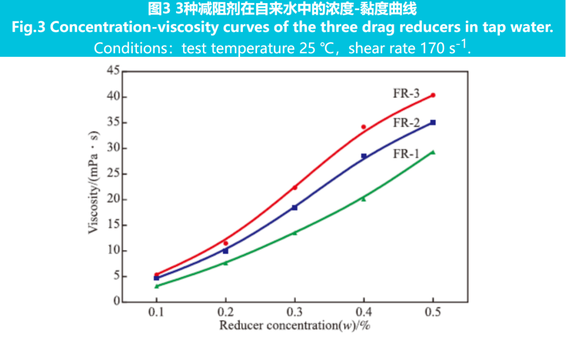
Figure 3 shows the concentration viscosity curves of three drag reducing agents in tap water.
From Figure 3, it can be seen that as the amount of drag reducing agent added increases, the viscosity of the slippery water increases. The viscosity of the slippery water prepared by two types of micro crosslinked drag reducing agents FR-2 and FR-3 is higher than that prepared by linear drag reducing agent FR-1. This is because the viscosity of the solution depends on the number and strength of entangled nodes (including cross-linking) between the polymers, and higher strength chemical cross-linking is introduced into the micro crosslinked drag reducing agent, resulting in stronger viscosity increasing ability than linear drag reducing agents. However, when the addition amount of micro crosslinking drag reducing agent exceeds 0.4% (w), the trend of viscosity increase slows down. This may be because at low addition amounts, chemical crosslinking has a higher proportion and greater effect in the entangled nodes, resulting in a significant increase in viscosity; As the amount of drag reducing agent increases, the proportion of chemical crosslinking decreases and the effect gradually decreases, so the trend of viscosity increase slows down.
From Figure 3, it can also be seen that FR-3 has a better viscosity increasing ability than FR-2, because the average number of functional groups of the crosslinking agent in FR-3 is higher, resulting in more cross-linking sites. According to the viscosity range of medium to high viscosity slippery water from 10 to 30 mPa·s, the dosage (w) of micro crosslinked drag reducing agents decreases by 20% to 30% compared to linear drag reducing agents, which can reduce liquid costs and reduce reservoir damage.


