


Case Studies
Case Studies
- Study on the Synthesis and Performance of a Large Temperature Difference Retarder for Oil Well Cement(Part 2)
- Study on the Synthesis and Performance of a Large Temperature Difference Retarder for Oil Well Cement(Part 1)
- Current Status and Development Trends of Key Technologies for Intelligent Oilfield (Part 1)
- Current Status and Development Trends of Key Technologies for Intelligent Oilfield (Part 2)
- Current Status and Development Trends of Key Technologies for Intelligent Oilfield (Part 3)
- New Developments in Oil Drilling Industry Technology
- Research and Application for the Fine Identification Method of Lost Circulation Characteristics During Drilling (Part 2)
- Research and Application for the Fine Identification Method of Lost Circulation Characteristics During Drilling (Part 1)
- Analysis of the Development Status and Trends of Unconventional Oil and Gas Cementing Materials (Part 1)
- Analysis of the Development Status and Trends of Unconventional Oil and Gas Cementing Materials (Part 2)
2.3.1 Prediction of Formation Pore Pressure
The X block has abundant logging data, with good continuity and high vertical resolution, which can better reflect the actual geological conditions. When using logging method to predict formation pore pressure, the main use is acoustic time difference, density logging and other data, which is convenient and applicable for prediction, and can calculate the profile of continuous changes in formation pore pressure with depth.
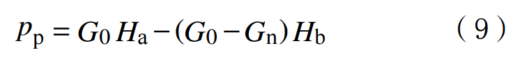
In the formula:G0 is the pressure gradient of the overlying rock layer, obtained from density logging data, MPa/m;Gn is the hydrostatic pressure gradient, MPa/m;Ha and Hb are the depth of the formation and the equivalent depth, respectively, m.
2.3.2 Prediction of Formation Rupture Pressure
The Poisson's ratio can reflect the formation fracture pressure, and can be calculated using acoustic logging data. Then, R A. Anderson's formation fracture pressure prediction model is used to calculate the formation fracture pressure.
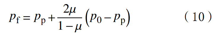
In the formula:μ is the Poisson's ratio;p0 is the pressure of the overlying rock layer,MPa.
2.3.3 Calculation of Wellbore Pressure
The wellbore pressure is the pressure exerted by the working fluid in the wellbore on the formation, which is the main driving force for wellbore leakage. Among them, wellbore pressure mainly includes static fluid column pressure of drilling fluid, annular pressure loss, and fluctuating pressure. In the actual drilling process, the fluctuation pressure only occurs at the moment of raising and lowering the drill bit, running the casing, stopping the pump, and starting the pump, and the fluctuation pressure is relatively small when operating normally, often negligible. Therefore, when determining wellbore pressure, the main considerations are the static fluid column pressure and annular pressure loss of the drilling fluid:
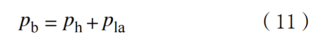
In the formula:ph is the static hydraulic column pressure of drilling fluid,MPa;plais the annular pressure loss,MPa.
The static hydraulic column pressure of drilling fluid is related to the density and vertical depth of the drilling fluid:
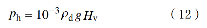
In the formula:ρd is the density of drilling fluid,kg/L;g is the gravitational acceleration,m/s2;Hv is vertical depth,m.
The drilling fluid in the wellbore circulation system mainly flows in the pipeline and annulus, resulting in annulus pressure loss. The Bingham model and power-law rheological model are commonly used in drilling engineering to calculate annular pressure loss. Among them, the Bingham mode is suitable for Bingham plastic fluids, while the power-law mode is suitable for pseudoplastic fluids and expanding fluids. The rheological performance analysis results of drilling fluid in Block X indicate that the drilling fluid used in this block is Bingham fluid. Therefore, the Bingham model is used to calculate the annular pressure loss:
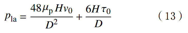
In the formula:μp is the plastic viscosity of drilling fluid,Pa·s;H is the depth of the well,m;v0 is the average flow rate of drilling fluid in the wellbore,m/s;τ0 is the yield value of drilling fluid,Pa;D is the inner diameter of the drill pipe,mm.
2.4 Analysis of Leakage Rate and Classification of Leakage Levels
2.4.1 Statistical Analysis Model for Leakage Rate
Statistical analysis was conducted on the data of leakage pressure difference, drilling fluid performance, and leakage velocity in the X block, and it was found that there is a good correlation between leakage pressure difference and leakage velocity. This article conducted least squares fitting on the leakage pressure difference and leakage velocity, and established the relationship between the leakage pressure difference and leakage velocity in Block X (see Figure 2). The power function fitting results showed the best correlation, with a fitting correlation coefficient of 0.8632.
.png)
After calculating the leakage pressure difference, the drilling fluid leakage rate can be determined:
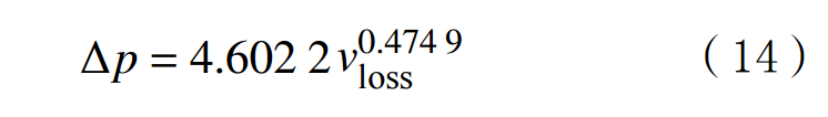
In the formula:vloss is the rate of drilling fluid leakage,m3/h.
2.4.2 Theoretical Analysis Model Derivation of Leakage Velocity
Drawing on the technical ideas of oilfield development water injection analysis, using the Darcy permeability formula and the basic differential equation of quasi steady state flow, a calculation model for leakage velocity under steady state and unstable state flow was established.
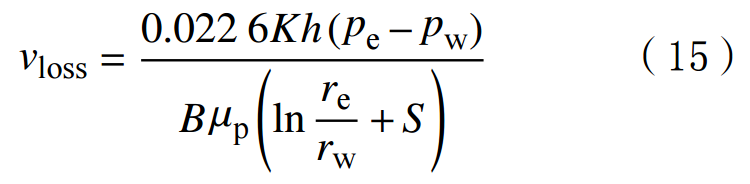
If the drilling fluid is in a stable flow state, the leakage rate derived using Darcy's law is:
If the drilling fluid is in an unstable flow state, the basic differential equation and boundary conditions for quasi steady state flow are:
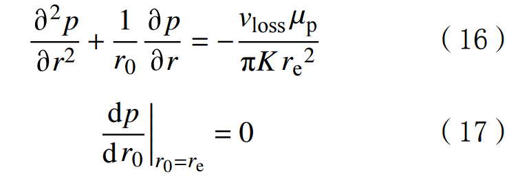
Substituting equations (16) and (17) into equation (15) yields:
In the formula:h is the thickness of the strata,m;pe is the boundary pressure of the area affected by well leakage,MPa;pw is the bottomhole pressure,MPa;pn is the static water pressure,MPa;B is the water volume coefficient;re is the intrusion radius,m;rw is the radius of the wellbore,m;S is the skin effect coefficient.
3. Example Analysis
The lithology of the X block is mainly composed of alternating layers of sandstone and mudstone. Based on the geological conditions, logging lithology profiles, and leakage statistics of the block, it is analyzed that the leakage in this area is mainly permeability leakage. Therefore, using a single pore mudstone logging interpretation model to calculate the lithology and physical parameters of well A in this block, combined with a multi information fusion method for identifying well leakage characteristics, the average pore throat radius, formation pore pressure, formation fracture pressure, wellbore pressure, loss rate, and comprehensive index of well leakage characteristics of the target formation are obtained. The processing results of the A well multi information fusion well leakage feature fine recognition method are shown in Figure 3.
.png)
From Figure 3, it can be seen that the wellbore pressure of the easily leaky formation in Well A is greater than the formation pore pressure but less than the formation fracture pressure, meeting the condition of differential pressure leakage. Among them, the comprehensive loss index of the 2900-2904 m and 2916-2919 m well sections is 0.81-0.98, and the radius of the horizontal pore throat in the formation is 4.46-4.67 μ m. The possibility of well leakage is high. Based on geological data and well logging interpretation results, the analysis determined that the vulnerable interval is a conglomerate formation, which is basically consistent with the corrected lithology logging profile. The leakage pressure difference is 7.11-9.46 MPa, and the calculated leakage rate is 2.5-4.5m3/h (micro leakage). During the actual drilling process of Well A, a leakage occurred in the 2901-2903 m section, with an average leakage rate of 1.5-52.0m3/h, indicating a permeable leakage. The lithology of the leakage layer is sandstone and gravel. The fine identification method of well leakage features was used to identify the location, type, and velocity of well leakage in Well A, which is basically consistent with the actual well leakage situation on site. The fine identification model of formation leakage characteristics has high credibility and is suitable for the identification of leakage characteristics in Block X. It can be applied to the comparison of formations in adjacent wells of Block X that are prone to leakage without drilling, as well as the identification of leakage characteristics based on adjacent well logging and on-site engineering data, providing theoretical model support for the subsequent drilling and development of the block. In actual drilling, the adjacent well of Well A was prepared with plugging slurry based on the fine identification results of the formation leakage characteristics, and the one-time plugging was successful, indicating that this method can guide on-site leak prevention and plugging operations.
4.Conclusions and Recommendations
1) Based on the basic conditions of well leakage and the characteristics of formation leakage in Block X, a fine identification method for well leakage characteristics using multi information fusion based on the "comprehensive index of well leakage" has been established. This method has a high accuracy in identifying the location of lost circulation layers, providing a technical approach for efficient prevention and control of lost circulation.
2) Logging data has the characteristics of good continuity and high vertical resolution. By using logging data for formation pore pressure and formation fracture pressure profiles, it can more accurately reflect the leakage pressure difference of the formation than traditional prediction methods. However, it is limited by the poor real-time performance of logging data and is suitable for predicting the leakage pressure difference of adjacent wells that have been drilled.
3) The fine identification method of multi information fusion for well leakage features can identify the main characteristic parameters of well leakage, such as leakage layer, leakage channel type and size, leakage pressure difference, leakage velocity, etc. The example analysis results show that it has good reliability. However, this method requires a high level of required parameter data, and in the absence of parameter data, it cannot effectively predict well leakage. Therefore, efforts should be made to study methods for accurately predicting the characteristics of well leakage when there is limited parameter data.