


Case Studies
Case Studies
- Study on the Synthesis and Performance of a Large Temperature Difference Retarder for Oil Well Cement(Part 2)
- Study on the Synthesis and Performance of a Large Temperature Difference Retarder for Oil Well Cement(Part 1)
- Current Status and Development Trends of Key Technologies for Intelligent Oilfield (Part 1)
- Current Status and Development Trends of Key Technologies for Intelligent Oilfield (Part 2)
- Current Status and Development Trends of Key Technologies for Intelligent Oilfield (Part 3)
- New Developments in Oil Drilling Industry Technology
- Research and Application for the Fine Identification Method of Lost Circulation Characteristics During Drilling (Part 2)
- Research and Application for the Fine Identification Method of Lost Circulation Characteristics During Drilling (Part 1)
- Analysis of the Development Status and Trends of Unconventional Oil and Gas Cementing Materials (Part 1)
- Analysis of the Development Status and Trends of Unconventional Oil and Gas Cementing Materials (Part 2)
To clarify the application scope of an innovative evaluation device for cementing flushing fluid, a calculation model for shear rates of Newtonian, Bingham and power-law fluids on external wall of the inner barrel was established in accordance with the Robertson-Stiff rheological model and with consideration to the equivalent shear rate on external wall of the inner barrel and on annular sidewall in cementing. In addition, errors between the shear rate of the external sidewall of inner barrel and that of cementing annual sidewall under different rheological modes was analyzed. Research results showed that the shear rate at the inner wall of the device is equal to that at the cementing interface with no theoretical error for Newtonian fluids, while the shear rate of the inner cylinder wall is higher than that on the cementing interface, and the increase in shear rates is related to the inner and outer cylinder gap and rheological properties of the flushing fluids for Bingham and the power-law fluids. When the diameter ratio between the outer and inner barrel is 1.04-1.20 and the flushing power-law fluid flow indexes over 0.6, or plastic viscosity below 1.0 Pa/(mPa·s) for Bingham fluid, their relative error in the shear rate can be maintained less than 10%. Research results show the smaller ratio between external and internal barrels diameter would cause less relative error, and the application scope of the device would be more extensive.
At present, the evaluation of cementing flushing fluids both domestically and internationally mostly uses the rotational viscometer method, which was first proposed by Berg in 1977. Although the rotary viscometer method is widely used, the simulated shear rate is single (the simulated wall shear rate is 340s-1), which cannot adapt to the shear rate changes under different well bore structures and annular return speeds, and has great limitations and deviations. In addition, there is a large centrifugal force when the outer cylinder rotates, which is greatly different from the actual situation on the site, and cannot accurately reflect the flushing effect of the flushing fluid on the cementing interface. Therefore, based on the principle that the shear rate at the inner and outer walls of the cementing annulus is equal to that of the evaluation device, this article studies a new flushing fluid evaluation method and device, which can be used for indoor evaluation of oil-based and water-based drilling fluid conditions in cementing flushing fluids. In order to achieve the best evaluation effect, the shear rate of the conventional rheological mode flushing solution at the inner and outer walls of the evaluation device was calculated. The applicable range of the evaluation device and the relative error between the theoretical shear rate and the experimental shear rate were analyzed, and the structure of the evaluation device was optimized.
1. Structure and Principle of a New Flushing Fluid Evaluation Device
1.1 Basic Structure
The new flushing fluid evaluation device mainly consists of rock core columns or steel columns, outer cylinders, conversion joints, transmission devices, motors, frames, support plates and slurry cups (see Figure 1). The device drives the outer cylinder to rotate through an electric motor to drive the flushing fluid to flush and fix the rock core column or steel column. By adjusting the speed of the outer cylinder and changing the size of the inner and outer cylinders, the shear rate of the outer wall of the inner cylinder is equal to that of the cementing annulus wall. This evaluation device not only evaluates the flushing effect of the flushing fluid, but also evaluates the wetting reversal of the flushing fluid on the cementing interface by changing the inner cylinder material (rock core or steel column), and optimizes the performance of the cementing flushing fluid based on the evaluation results.
.png)
1.2 Evaluation principle
The new flushing fluid evaluation device simulates the flow of flushing fluid in the annular space between the casing and the wellbore through the flow between two coaxial cylinders (see Figure 2), and evaluates the flushing efficiency of the flushing fluid based on the theory that the shear rates of the two are equal. During cementing operations, the cementing construction parameters (such as the type of flushing fluid, flushing time, and flushing flow rate) can be optimized based on the evaluation results of the flushing fluid.
.png)
The shear rate at the cementing interface between the casing and the annular wall of the wellbore is:
.png)
Where: γh is the shear rate at the annular wall surface,s-1;ν is the average return velocity in the annulus,m/s;D is the diameter of the wellbore,m;d is the outer diameter of the casing,m.
The shear rate at the outer wall of the fixed inner cylinder of the evaluation device is:
.png)
Where: γ1 is the shear rate at the outer wall of the inner cylinder,s-1;N is the outer cylinder speed, r/min;R2 is the inner radius of the outer cylinder, mm; R1 is the outer radius of the inner cylinder, mm.
When using the new flushing fluid evaluation device to evaluate the flushing efficiency of the flushing fluid, γh and γ1 are made equal by adjusting the outer cylinder speed or changing the inner radius of the outer cylinder and the outer radius of the inner cylinder.
2.Adaptability Analysis of the new Flushing Fluid Evaluation Device under different Rheological Modes
Take any layer of liquid with a circular gap radius of x, its angular velocity is wx, the side area of the liquid layer is Sx=2πxh, and the rotational torque is Mx=2πx2hτx.
The shear rate γx at radius x is:
.png)
Transforming formula (3) yields:
.png)
Because 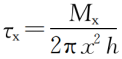 , so:
, so:
.png)
Substituting formula (5) into formula (4) yields:
.png)
When x=R1, it will be wx=0,τx=τ1;
When x=R2, it will be wx=w,τx=τ2.
Integrating formula (6) yields:
.png)
Where: x is the radius of any annular gap, m;τx is the shear stress of the liquid layer at the radius x of the annular gap, Pa;γx is the shear rate of the liquid layer at radius x, s-1;τ1 is the shear stress of the liquid layer at the outer radius of the inner cylinder, Pa;τ2 is the shear stress of the liquid layer at the inner radius of the outer cylinder, Pa; wx is the angular velocity of the liquid layer at the radius x of the annular gap, rad/s;h is the height of the inner cylinder, m.
Formula (7) can be used to evaluate the relationship between shear rate, shear stress, and rotational angular velocity at any annular gap radius of the device. This article uses the Robertson-Stiff model, which can describe three conventional rheological modes Newton, Bingham and power-law, to calculate the shear rate at the inner and outer walls of the flushing fluid under different rheological modes.
The shear rate formula for Robertson-Stiff rheological mode is:
.png)
Where: A is the consistency coefficient, Pa · sn; B is the liquidity index; C is the shear dilution coefficient, s-1.
Substituting formula (8) into formula (7) yields:
.png)
Integrating formula (9), and also substituting 后面的图片.png) into (9) yields:
into (9) yields:
.png)
Transforming formula (10) and combining it with formula (8) to obtain:
.png)
Substituting 前面的图片.png) into formula (11), the shear rate at the outer wall of the inner cylinder of the evaluation device is obtained:
into formula (11), the shear rate at the outer wall of the inner cylinder of the evaluation device is obtained:
.png)
Analyzing formula (12) to discuss the shear rate at the outer wall of the inner cylinder under different rheological modes.
1) When B=1 and C=0, it is a Newtonian rheological mode, and the shear rate at the outer wall of the inner cylinder of the evaluation device is:
.png)
2) When B=1 and C ≠ 0, it is the Bingham rheological mode, and the shear rate at the inner and outer walls of the evaluation device is:
.png)
Where:
和(16).png)
τ0 is the dynamic shear force of the fluid in the Bingham rheological mode, Pa;
ηp is the plastic viscosity of the fluid in the Bingham rheological mode, Pa · s.
3) When B ≠ 1 and C=0, it is a power-law rheological mode, and the shear rate at the outer wall of the inner cylinder of the evaluation device is:
.png)